

Ethernet
Ethernet is a widely deployed LAN technology.This technology was invented by Bob Metcalfe and D.R. Boggs in the year 1970. It was standardized in IEEE 802.3 in 1980.
Ethernet shares media. Network which uses shared media has high probability of data collision. Ethernet uses Carrier Sense Multi Access/Collision Detection (CSMA/CD) technology to detect collisions. On the occurrence of collision in Ethernet, all its hosts roll back, wait for some random amount of time, and then re-transmit the data.
Ethernet connector is,network interface card equipped with 48-bits MAC address. This helps other Ethernet devices to identify and communicate with remote devices in Ethernet.
Traditional Ethernet uses 10BASE-T specifications.The number 10 depicts 10MBPS speed, BASE stands for baseband, and T stands for Thick Ethernet. 10BASE-T Ethernet provides transmission speed up to 10MBPS and uses coaxial cable or Cat-5 twisted pair cable with RJ-45 connector. Ethernet follows star topology with segment length up to 100 meters. All devices are connected to a hub/switch in a star fashion.
Fast-Ethernet
To encompass need of fast emerging software and hardware technologies, Ethernet extends itself as Fast-Ethernet. It can run on UTP, Optical Fiber, and wirelessly too. It can provide speed up to 100 MBPS. This standard is named as 100BASE-T in IEEE 803.2 using Cat-5 twisted pair cable. It uses CSMA/CD technique for wired media sharing among the Ethernet hosts and CSMA/CA (CA stands for Collision Avoidance) technique for wireless Ethernet LAN.
Fast Ethernet on fiber is defined under 100BASE-FX standard which provides speed up to 100 MBPS on fiber. Ethernet over fiber can be extended up to 100 meters in half-duplex mode and can reach maximum of 2000 meters in full-duplex over multimode fibers.
Giga-Ethernet
After being introduced in 1995, Fast-Ethernet could enjoy its high speed status only for 3 years till Giga-Ethernet introduced. Giga-Ethernet provides speed up to 1000 mbits/seconds. IEEE802.3ab standardize Giga-Ethernet over UTP using Cat-5, Cat-5e and Cat-6 cables. IEEE802.3ah defines Giga-Ethernet over Fiber.
Virtual LAN
LAN uses Ethernet which in turn works on shared media. Shared media in Ethernet create one single Broadcast domain and one single Collision domain. Introduction of switches to Ethernet has removed single collision domain issue and each device connected to switch works in its separate collision domain. But even Switches cannot divide a network into separate Broadcast domains.
Virtual LAN is a solution to divide a single Broadcast domain into multiple Broadcast domains. Host in one VLAN cannot speak to a host in another. By default, all hosts are placed into the same VLAN.
In this diagram, different VLANs are depicted in different color codes. Hosts in one VLAN, even if connected on the same Switch cannot see or speak to other hosts in different VLANs. VLAN is Layer-2 technology which works closely on Ethernet. To route packets between two different VLANs a Layer-3 device such as Router is required.
Computer Network Topologies
A Network Topology is the arrangement with which computer systems or network devices are connected to each other. Topologies may define both physical and logical aspect of the network. Both logical and physical topologies could be same or different in a same network.
Point-to-Point
Point-to-point networks contains exactly two hosts such as computer, switches or routers, servers connected back to back using a single piece of cable. Often, the receiving end of one host is connected to sending end of the other and vice-versa.

If the hosts are connected point-to-point logically, then may have multiple intermediate devices. But the end hosts are unaware of underlying network and see each other as if they are connected directly.
Bus Topology
In case of Bus topology, all devices share single communication line or cable.Bus topology may have problem while multiple hosts sending data at the same time. Therefore, Bus topology either uses CSMA/CD technology or recognizes one host as Bus Master to solve the issue. It is one of the simple forms of networking where a failure of a device does not affect the other devices. But failure of the shared communication line can make all other devices stop functioning.
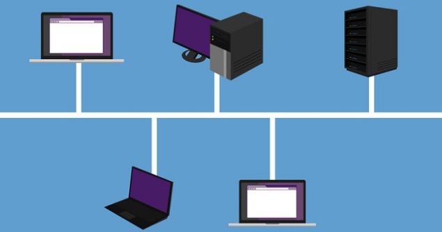
Both ends of the shared channel have line terminator. The data is sent in only one direction and as soon as it reaches the extreme end, the terminator removes the data from the line.
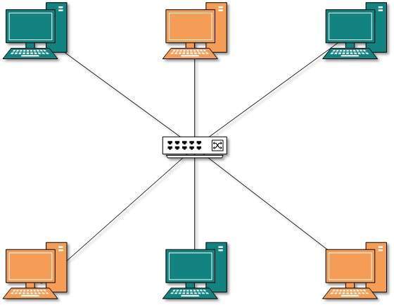
Star Topology
All hosts in Star topology are connected to a central device, known as hub device, using a point-to-point connection. That is, there exists a point to point connection between hosts and hub. The hub device can be any of the following:
- Layer-1 device such as hub or repeater
- Layer-2 device such as switch or bridge
- Layer-3 device such as router or gateway
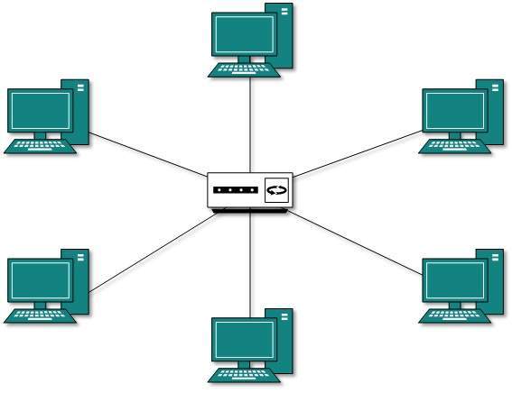
As in Bus topology, hub acts as single point of failure. If hub fails, connectivity of all hosts to all other hosts fails. Every communication between hosts, takes place through only the hub.Star topology is not expensive as to connect one more host, only one cable is required and configuration is simple.
Ring Topology
In ring topology, each host machine connects to exactly two other machines, creating a circular network structure. When one host tries to communicate or send message to a host which is not adjacent to it, the data travels through all intermediate hosts. To connect one more host in the existing structure, the administrator may need only one more extra cable.
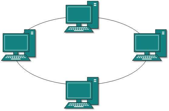
Failure of any host results in failure of the whole ring.Thus, every connection in the ring is a point of failure. There are methods which employ one more backup ring.
Mesh Topology
In this type of topology, a host is connected to one or multiple hosts.This topology has hosts in point-to-point connection with every other host or may also have hosts which are in point-to-point connection to few hosts only.
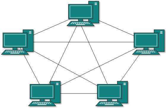
Hosts in Mesh topology also work as relay for other hosts which do not have direct point-to-point links. Mesh technology comes into two types:
- Full Mesh: All hosts have a point-to-point connection to every other host in the network. Thus for every new host n(n-1)/2 connections are required. It provides the most reliable network structure among all network topologies.
- Partially Mesh: Not all hosts have point-to-point connection to every other host. Hosts connect to each other in some arbitrarily fashion. This topology exists where we need to provide reliability to some hosts out of all.
Tree Topology
Also known as Hierarchical Topology, this is the most common form of network topology in use presently.This topology imitates as extended Star topology and inherits properties of bus topology.
This topology divides the network in to multiple levels/layers of network. Mainly in LANs, a network is bifurcated into three types of network devices. The lowermost is access-layer where computers are attached. The middle layer is known as distribution layer, which works as mediator between upper layer and lower layer. The highest layer is known as core layer, and is central point of the network, i.e. root of the tree from which all nodes fork.
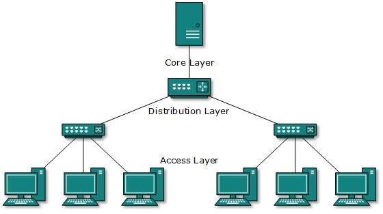
All neighboring hosts have point-to-point connection between them.Similar to the Bus topology, if the root goes down, then the entire network suffers even.though it is not the single point of failure. Every connection serves as point of failure, failing of which divides the network into unreachable segment.
Daisy Chain
This topology connects all the hosts in a linear fashion. Similar to Ring topology, all hosts are connected to two hosts only, except the end hosts.Means, if the end hosts in daisy chain are connected then it represents Ring topology.

Each link in daisy chain topology represents single point of failure. Every link failure splits the network into two segments.Every intermediate host works as relay for its immediate hosts.
Hybrid Topology
A network structure whose design contains more than one topology is said to be hybrid topology. Hybrid topology inherits merits and demerits of all the incorporating topologies.
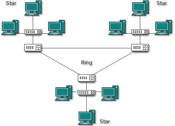
The above picture represents an arbitrarily hybrid topology. The combining topologies may contain attributes of Star, Ring, Bus, and Daisy-chain topologies. Most WANs are connected by means of Dual-Ring topology and networks connected to them are mostly Star topology networks. Internet is the best example of largest Hybrid topology.
No comments:
Post a Comment